Digital S-Meter for CB Radio
Digital S-Meter for CB Radio
This module is part of the larger project to fit two displays to a Jopix, but I am sharing it separately in case anyone wants to build it on its own.
It may not be the most professional or the most elegant, but it works well, it is accurate and it costs less than €20. On top of that, it adapts to almost any radio. You just have to change the measurement table in the code to match your radio’s S-meter voltage. In this case, the code is tuned for a Super Star 3900, or any other rig with the same board.
How hard this project really is
If you ask me now, on a scale of 1 to 10, I would say this is a 2. But of course… I say that now. At the start it was not so easy. When you do not know the first thing about electronics and you set out to design a circuit with the help of an AI, it feels less like programming and more like interrogating ChatGPT, looking for inconsistencies like an old cop with a hangover.
Designing the circuit
It all started with a simple idea: “my radio has an analog S-meter with two wires; I want to replace it with a little screen driven by an ESP32.” I threw that at ChatGPT and it answered with a confidence that was almost scary. But you know how this goes: everything the AI says has to be double-checked, line by line.
You explain your vision, and it spits out code and schematics as if it were all plug & play. But you have to go into bloodhound mode: ask it the same question several times, rephrase it, poke at the seams… until you can tell whether what it is proposing is viable or it is just making it up.
The component drama
When you think you finally have something decent, another odyssey begins: ordering the components. If you are new, every purchase raises doubts. “Do I order this screen or that one?”, “Will this sensor work?” Because if you get it wrong, that is 15 days of waiting and more uncertainty.
And of course, I got it wrong. From the first order, two things were no good: the screen and the voltage sensor.
The screen was too small. Even the basic interface would not fit. But it was useful for testing everything else.
Then, the voltage sensor. According to ChatGPT, the ESP32 cannot read the S-meter voltage directly, so it recommended adding a measurement module. The problem: that module had the same minimum range as the ESP32 itself, so it did not help at all.
I placed a second order with a slightly larger screen and a more suitable measurement module.
Getting to work
Two weeks later, back at it.
I set everything up on a breadboard and started on the code. The idea was clear: the ESP32 had to read the S-meter voltage, interpret it and display it visually on screen with a graphical interface.
Here came another obstacle: ChatGPT had no idea of the actual voltage the Jopix S-meter works with. It gave me a rough table, but without real data it was like painting blindfolded.
Luckily, I called on a contact. I asked Rubén (EA5PR) for help, and he sent me a table of the real values used to calibrate these radios. In theory, that should have been enough for an accurate reading… but of course, that would be the case only if the voltage module were properly adjusted.
Spoiler: it was not.
I had to fall back on the crudest method: trial and error. I manually adjusted the sensitivity until it covered the whole useful range. Then, with the analog S-meter recently calibrated, I noted down the voltage at every half S-point, from 0 to +45.
More complications
Using the traditional S scale (1, 3, 5, 7, 9, +40) seemed easy… but when I drew the needle on the screen, it did not land properly on the reference values.
So I got the most tedious part: mapping the screen pixel by pixel and tweaking the code so the graphical markers matched the real data. I am not exaggerating when I say I spent several nights on that. For some reason, the AI could not get it right — not the first time, and not the twentieth.
All set
If you already have experience, you can swap the ESP32 for a smaller or more minimal microcontroller. But if you change any component, you will have to adapt the code.
If you do not have experience and want to reproduce this project as is, use exactly the same components I did. That way you save yourself hours of unnecessary suffering.
Component list
ESP32-WROOM
0.91-inch OLED module
ADS1115
100 nF capacitor
16 V 100 µF capacitor
PCB protoboard (optional)
Pin header (optional)
Dupont cables, at least female-to-female
A push button of your choice that fits the look you want
Circuit and wiring
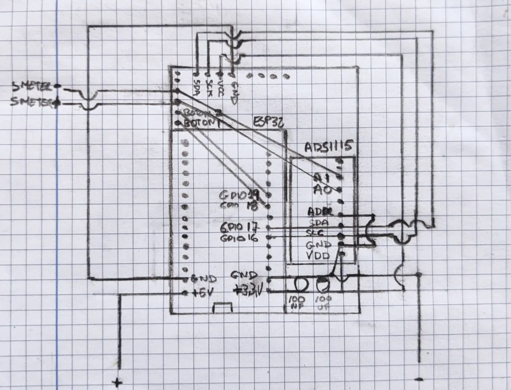
This is the wiring diagram for the components, leaving quick pin connectors for the screen, the S-meter voltage signal and the button that switches between the different customization themes.
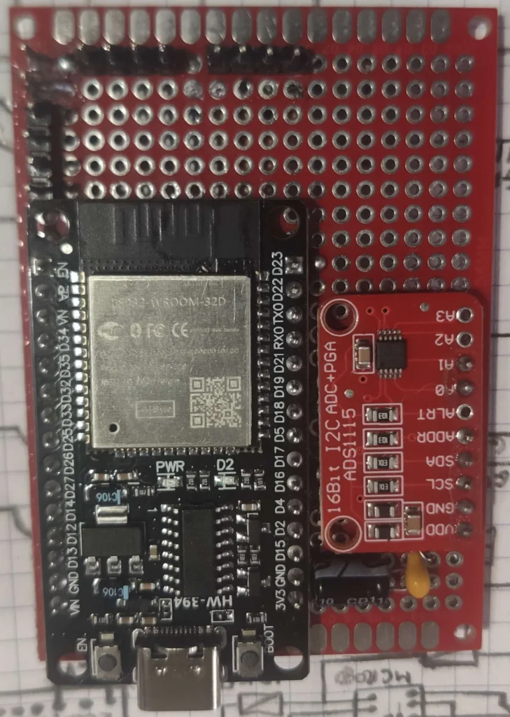
Assembled on a board, the module looks something like what you see in the photo. You can use a smaller board with no problem; I used this one because I also have to integrate the circuit for the second display later on.
In the image you can see there are more pins than needed: 14 are shown, but only 8 are used. The rest are for the other display, not because they are needed for the digital S-meter to work.
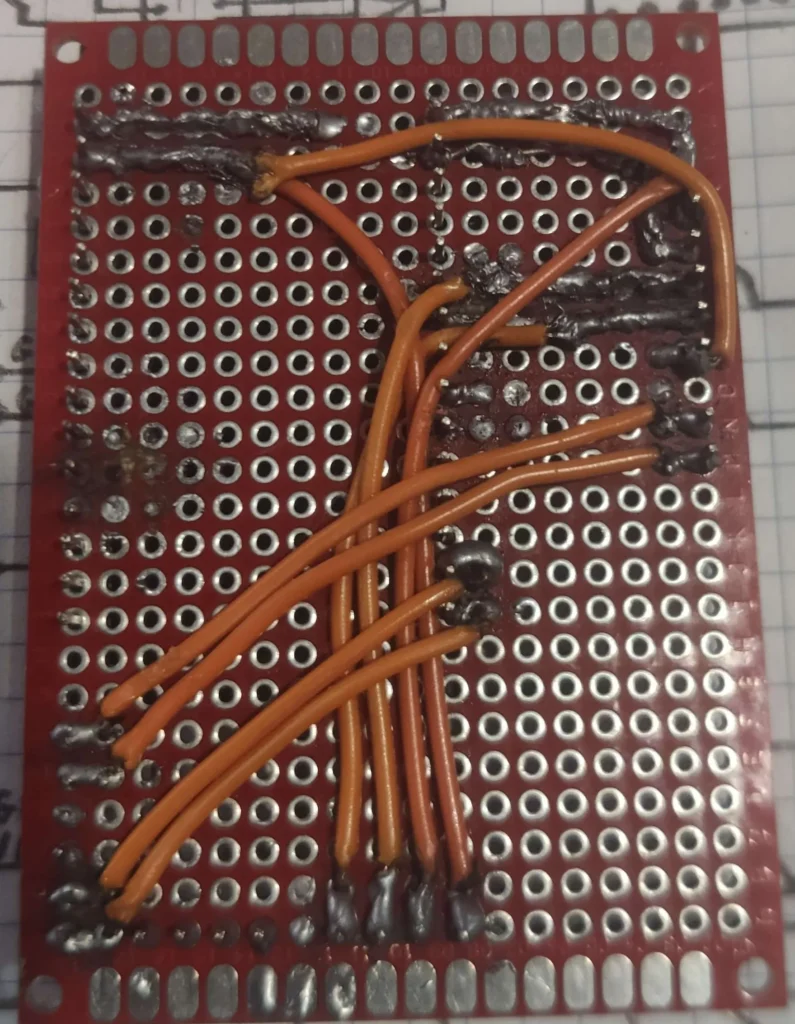
And here is an image of the back of the build, where you can clearly see the tracks and connections. Do not be alarmed if mine looks a bit scrappy to you — what matters is that it works.
If you are any good with your hands, yours will surely come out much neater. And if not, no big deal: you can make all the connections with Dupont cables without soldering anything or building the circuit on a board.
This is about learning, not about making a work of art on the first try.
To work on developing the software and run all the necessary tests, I first built the circuit on a classic breadboard, the old-fashioned kind. That is where I refined the code, calibrated the readings and adjusted the display.
Once everything worked as it should, I moved the build to a PCB-type protoboard, much more compact and ready to install inside the radio.
Here is a video of the module fully assembled and ready to be fitted into the rig:
The firmware
Here are the two files you need to flash the firmware onto the ESP32 using PlatformIO. If you have reproduced exactly the same components and wiring, it should work without any drama.
Temporarily unavailable. Pending new adjustments.
📁 What you need
platformio.ini→ Environment configurationmain.cpp→ Main code for the digital S-meter
⚠️ Important
In the platformio.ini file, make sure you specify the correct port your ESP32 is connected to. Otherwise, PlatformIO will not know where to upload the code.
Not measuring correctly?
If, when you start it up, you see that the readings do not match reality, it is time to roll up your sleeves. You will have to adjust the values in the voltage table manually so they fit your radio.
How to use it and how to read the scale
Using it is no mystery: as soon as it gets power, the module starts working automatically.
It also includes a button that lets you change the display theme (in case you get bored of the same background all the time).
🧭 Reading scale
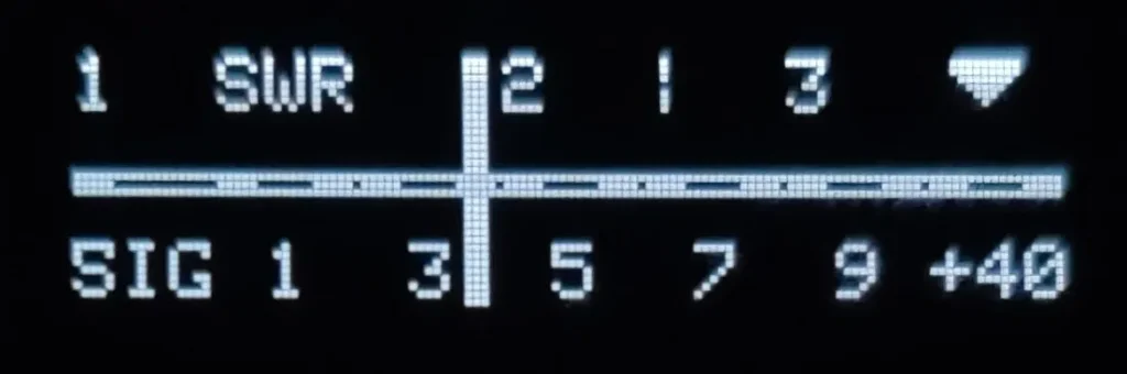
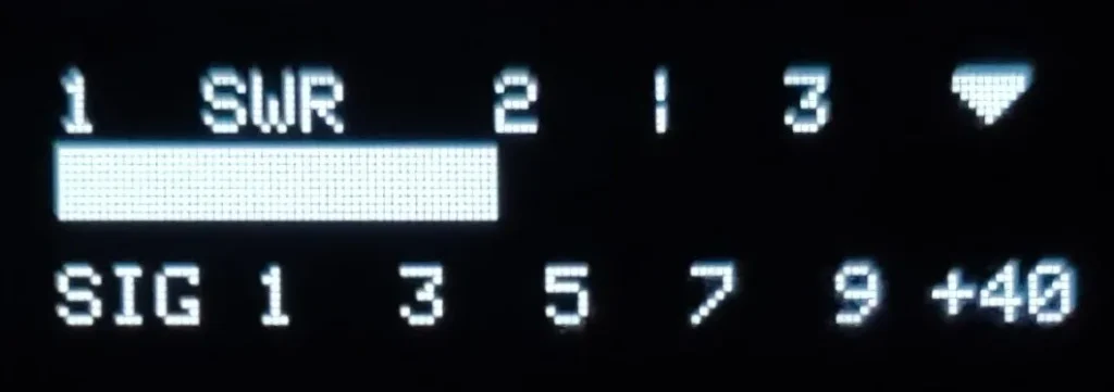
The scale shown on screen follows the classic format:
SIG 1, 3, 5, 7, 9, +40
And you read it like this:
| Símbolo | Equivalencia en S |
|---|---|
| S | 0 |
| G | 0.5 |
| 1 | 1 |
| 3 | 3 |
| 5 | 5 |
| 7 | 7 |
| 9 | 9 |
| + | +30 |
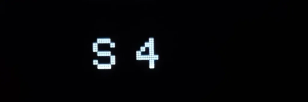
| 4 | +40 |
| 0 | > +45 |
The default measurement is in steps of 0.5 S from 0 to 9.
The midpoint between two numbered marks represents an intermediate reading. For example:
- If the indicator is between S7 and S9 → you are receiving an S8 signal.
- If it is halfway between S7 and S8 → it reads S7.5.
This gives much more precision than the classic needle.
By the way:
The “4” symbol on the +40 scale also serves as a calibration reference for measuring SWR.
3 themes to choose from
The firmware includes three different display themes so you can pick whichever you like best at any time.
Just press the button to switch the display between themes.
Powering the module
The ESP32 runs at 5 V, but your rig works at 12 V, so you cannot connect it directly unless you want to fry it on the first go.
To adapt it, you need a DC-DC converter that steps the voltage down in a stable way.
Go back to the main project page, where I explain which converter I use and how I have it wired to power the circuit safely.
Frequently Asked Questions
Can I use an OLED screen instead of the TFT you use?
Technically yes, but I would not recommend it if you do not have experience. Changing the screen means modifying both the code and the graphics libraries, and adapting resolutions, colors, coordinates… In short, it is a different project. If you want it to work first time, use the same one I did.
What if I use a different voltage sensor?
Same thing: you can, but you will have to modify the code. Each sensor has a different range and gives different readings, so you will have to redo the calibration table. If you do not know what you are doing, you will not measure anything accurately.
Can I use a different microcontroller instead of the ESP32?
Yes, you can use an ESP8266 or even something smaller, but you will have to adapt the wiring, the code logic and the display handling. If you already know your way around this, go ahead. If not, better not to get tangled up in it.
Is this compatible with any rig?
Almost. The module adapts to any radio that has an analog S-meter, as long as you can get to the needle meter’s wires. All you have to do is change the voltage table in the code to match how your radio behaves.
Wrapping up the first piece of the puzzle
This digital S-meter is just a small piece within a much more ambitious project, but it stands for something important: proof that you can modernize a classic rig without spending a fortune or having a master’s degree in electronic engineering.
Can it be done better? Sure. Can it be simplified? Also. But what matters is that it works, it is reproducible and, above all, it teaches. Because what you learn adjusting voltages, calibrating a screen or fighting with libraries is worth far more than the trivial end result itself.
So if you decide to build your own, you know the drill: copy, test, break, tweak… and share. That is what we are here for.
And if something does not fit, or you want to go all in with improvements, drop me a line. We are here to tinker.