Antenna rotator controller with azimuth and elevation
Today we’re sharing a project that’s especially interesting for any ham who wants to take a serious step up in antenna control: a rotator controller with azimuth and elevation, compatible with most common amateur radio software.
It’s an ideal solution for automatic satellite tracking, letting the antenna follow the pass precisely and with no manual intervention. No aiming by eye, no reliance on closed proprietary controllers: this is a reproducible, modern system meant to actually be used.
Work by Juan Manuel, EA7KWF
This work comes from Juan Manuel (EA7KWF), whom I met in the Riojanos por la Radio community. He’s one of those people it’s easy to talk shop with: he shares, he explains, and he doesn’t keep anything up his sleeve.
One of his latest projects is exactly this rotator controller, and he has generously offered to bring it to Acuántico Power as a step-by-step guide, so that anyone can replicate it at home.
Exactly what you’ll build
The end result of this project is a WiFi rotator controller capable of moving:
- Azimuth (up to 450°)
- Elevation (up to 180°)
All of it through GS-232A commands, the protocol understood by most control and satellite-tracking programs used in amateur radio.
The system is based on an ESP32, which acts as the brain of the setup: it receives commands over the network and translates them into real movement using stepper motors.
What the system does
As the code is implemented:
- The ESP32 connects to your WiFi network
- It uses a static IP
- It opens a TCP server on port 4533
- It interprets standard GS-232A commands
- Controla dos motores paso a paso:
- One for azimuth
- The other for elevation
What you’ll need
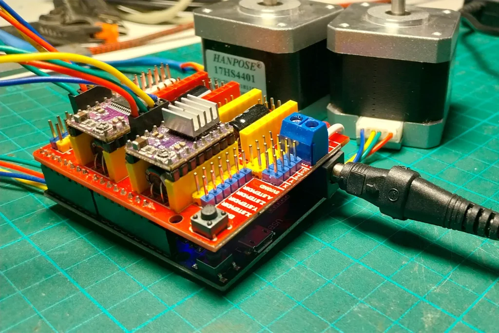
Main components
Before you start, it helps to have everything on the table.
- 1 × ESP32 Dev Module
- 2 × stepper motor drivers (DRV8825 Kit)
- 2 × stepper motors (recommended: NEMA 17)
- 1 × power supply for the motors (12V 4A)
- Connection wires
- 1 × USB cable to program the ESP32
Recommended
- Heatsinks for the drivers (included in the DRV8825 kit)
- Basic ventilation if the rotator moves any real load
Wiring the components
The code explicitly defines which pins are used, but in practice you don’t need to wire pin by pin.
Using an ESP32 board together with a CNC Shield, the setup is designed to fit directly, with no way to get the orientation wrong.
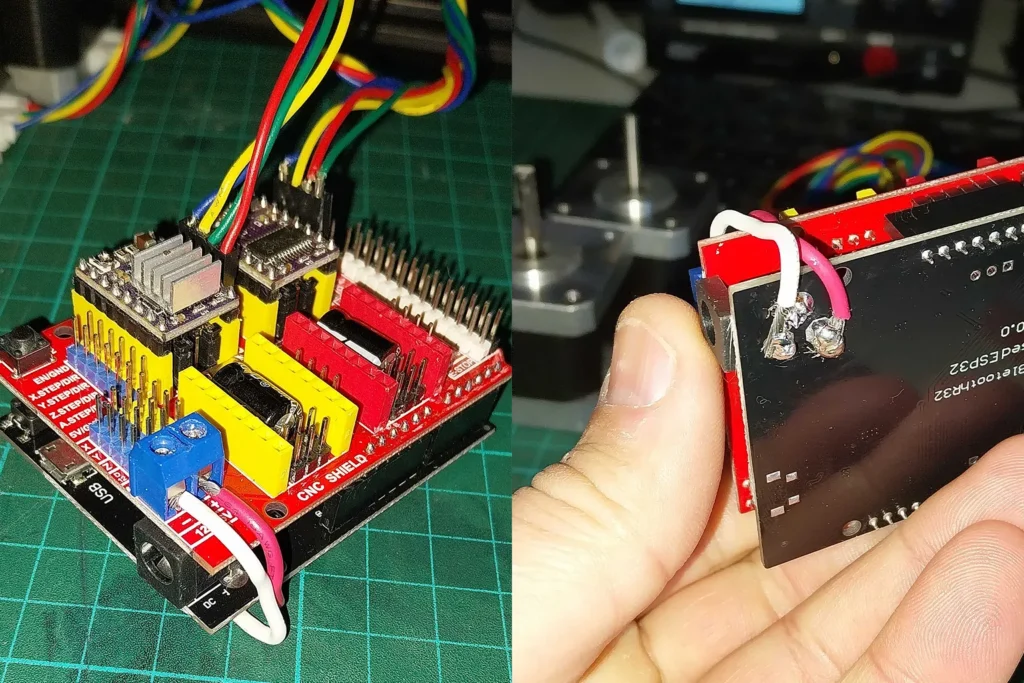
The CNC Shield has only one possible position on top of the base board, so you just place it correctly and press until it’s properly seated.
Once it’s in place, all you have to do manually is wire the shield’s power the same way as in the following image:
Fitting the motor drivers
This project only uses two axes:
- X axis → azimuth
- Y axis → elevation
So:
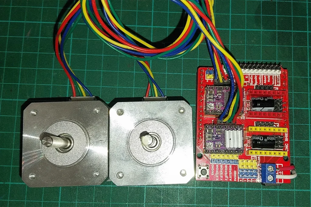
- You need to fit two stepper motor drivers in the X and Y positions of the CNC Shield.
- The usual kit includes 4 drivers, so you’ll have 2 left over.
- You can also buy the CNC Shield and just two drivers separately.
It’s important to respect the driver’s orientation when inserting it into the board, aligning the pins correctly. Never force it in.
Setting the driver voltage (VREF)
Before connecting the motors, it’s essential to set the reference voltage (VREF) of each driver.
This setting limits the maximum current the motor will receive and prevents overheating or damage.
The adjustment is done with the potentiometer built into each driver.
How to calculate VREF
The rule used in this project is simple:
VREF = motor’s maximum current / 2
In this case, 1.7 A motors are used, so the reference value will be roughly:
VREF ≈ 0.8 V
How to measure it
- Use a multimeter
- Put the negative probe on GND
- Measure the voltage at the driver’s potentiometer
- Adjust by gently turning the screw until you get the value you want
Juan Manuel explains this process very clearly in PART 4 of the videos, which you’ll find further down in this article.
Setting up the programming environment
Installing the Arduino environment
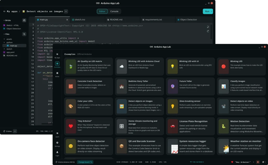
The whole project is compiled from the official Arduino environment, available for Windows, Linux and macOS.
Adding ESP32 support
To work with ESP32 boards you need to install support from the manufacturer, Espressif Systems.
In the Arduino IDE:
- Open Preferences
- Add this URL under “Additional boards manager URLs”:
https://raw.githubusercontent.com/espressif/arduino-esp32/gh-pages/package_esp32_index.json- Install the ESP32 package from the boards manager
Installing the required library
Motor control is handled by the AccelStepper library, which you install directly from the IDE’s library manager.
Firmware
WiFi configuration
Before uploading the program, you only need to change these values in the code from the editor:
const char* ssid = “YOUR_WIFI_NAME”;
const char* password = “YOUR_WIFI_PASSWORD”;
And check that the static IP you want to assign is free and matches your local network’s ranges:
IPAddress local_IP(192,168,0,50); The IP your ESP32 will have.
IPAddress gateway(192,168,0,1); Your router’s IP.
IPAddress subnet(255,255,255,0); The same.
If your network doesn’t use the 192.168.0.x range, adjust these values before continuing, for example to 192.168.1.x.
Uploading the program to the ESP32
- Connect the ESP32 to the computer via USB
- En el IDE selecciona:
- Board: ESP32 Dev Module
- Port: the one that appears when you connect the board
- Click Upload
If the process finishes without errors, the controller is now programmed.
Software needed to run the controller
For the rotator controller to work properly from the computer, the electronics alone aren’t enough.
You need two pieces of software that act as a bridge between the amateur radio program and the WiFi controller.
Hamlib
The project uses Hamlib, a library widely used in amateur radio to control equipment such as:
- Antenna rotators
- Transceivers
- Satellite tracking systems
Many amateur radio programs don’t talk directly to the hardware; they do it through Hamlib.
In this case, Hamlib takes care of translating the software’s commands (for example, move the antenna to a specific position) into the format the GS-232A controller understands.
In the article about my tool Hamlib Launcher there’s a complete installation tutorial for Hamlib.
HW-VSP3 (Virtual Serial Port)
Besides Hamlib, you need to install HW‑VSP3
This program creates a virtual serial port in the operating system.
What’s it for?
- Many amateur radio programs expect to communicate with a rotator through a COM port
- Our controller works over the network (TCP/IP)
- HW-VSP3 actúa como traductor entre ambos mundos:
- The software thinks it’s talking to a serial port
- In reality, the data is sent over the network to the ESP32
Thanks to this, the controller is compatible with software originally designed for classic RS-232 rotators.
First check
Open the IDE’s Serial Monitor and set the speed to 115200 baud.
When you restart the board you should see:
- WiFi connection messages
- The assigned IP
- The active TCP server
That means the system is ready to receive commands.
Testing GS-232A control
From any compatible software or via a Telnet connection:
- IP: the ESP32’s
- Port: 4533
Basic commands:
C→ returns the current positionW180 045→ moves to azimuth 180°, elevation 45°S→ stops the movement
If the motors respond correctly, the controller is working.
Video documentation
Besides this step-by-step guide, Juan Manuel (EA7KWF) has published a series of videos on his YouTube channel documenting the whole process in detail.
This video material is especially useful for:
- Seeing the project working for real
- Getting a better grasp of the physical assembly
- Clearing up specific questions while flashing the firmware or wiring the motors
If at some point in the build you’re left with a question, these videos will help you tie up loose ends without improvising.
LOW-COST ANTENNA ROTATOR FOR SATELLITE TRACKING – PART 1 – General overview of the project and a working demo
LOW-COST ANTENNA ROTATOR FOR SATELLITE TRACKING – PART 2 – Detailed explanation of the motor controller module
LOW-COST ANTENNA ROTATOR FOR SATELLITE TRACKING – PART 3 – How to flash the firmware onto the controller
LOW-COST ANTENNA ROTATOR FOR SATELLITE TRACKING – PART 4 – Wiring the stepper motors
Some videos used an Arduino that would later be replaced by an ESP32. In practice, that detail doesn’t matter here.
You can also visit the author’s GitHub.
The project continues
This controller isn’t an end point, but a starting point.
Juan Manuel, the project’s author, is already working on the mechanical side: a reduction system, antenna mounts and everything needed to have a complete antenna rotator, designed specifically for satellite tracking.
The idea is to close the loop:
electronics, control, mechanics and real use at the station, with no improvised solutions or external dependencies.
From Acuántico Power we’ll be sharing the upcoming updates as the project moves forward.
If this kind of development interests you, stay tuned.
The best of this rotator is still to come.